MIPI Viewer User Guide
References
Application version: 1.0.0
Document reference |
UG033 |
Document revision |
A |
Generation date |
23 Oct. 2026 |
Written by |
F. DESCAMPS |
22 Oct. 2026 |
Validated by |
- |
- |
Approved by |
K. TOUTAIN |
23 Oct. 2026 |
Related documents:
UG026MIPI-A1 Interface Board UserGuideUG028MD-MZ-I313 UserGuideUG034MIPI software pack installation UserGuideUG035DB-MIPI-A1 Driver UserGuideUG032MD-MZ-I313 Driver UserGuideUG042MIPI-A1 ClockGen Calculator UserGuide
Abbreviation table
ADC |
Analog-to-Digital Converter |
BMP |
Bitmap image file |
FPGA |
Field-Programmable Gate Array |
FPA |
Focal Plane Array |
FPN |
Fixed Pattern Noise |
fps |
Frames Per Second |
GUI |
Graphical User Interface |
I2C |
Inter-Integrated Circuit |
ISP |
Image Signal Processor |
MIPI |
Mobile Industry Processor Interface |
NUC |
Non-Uniformity Correction |
SPI |
Serial Peripheral Interface |
TOML |
Tom’s Obvious Minimal Language |
VTemp |
Sensor temperature voltage |
Introduction
MIPI Viewer shows the live video of:
a FullScale Proxy board connected through a FullScale MIPI board.
a MIPI based FullScale module.
It lets the operator tune the image, capture it and access the registers of the setup’s components.
Note
The application runs on the Raspberry Pi 4 and Raspberry Pi 5 under Raspberry Pi OS, and on the NVIDIA Jetson Orin Nano developer kit.
Boards and setups
Two things are told apart throughout the application:
Term |
Meaning |
|---|---|
MIPI board |
The board on a CSI connector of the acquisition system, such as the MIPI-A1
Interface Board or the MD-MZ-I313. The viewer finds it through its
Linux driver, |
Setup |
The MIPI board and what is behind it, as the configuration file describes them: the proxy board mounted on it, or the proxy a module embeds, the frame size, the clock, which components the board can reach, and the registers to write when it starts. A setup is picked by its proxy, and may come in several variants, with or without a shutter, or at several frame rates. |
The board is found by the viewer; the setup is chosen by the operator, from the setups the configuration file declares for that board’s driver. See The configuration file.
Each board has a window of its own. Two boards are two windows, each with its own setup, stream, tuning and captures.
Installation
Refer to UG034 for the installation of MIPI Viewer and of the drivers of
the MIPI boards.
Starting the viewer
Start MIPI Viewer from the FullScale Tools menu, or with
mipi-viewer in a terminal. What opens depends on the MIPI boards found:
Boards found |
The viewer opens |
|---|---|
One |
That board’s window, straight away. |
Several |
The board chooser, to pick one, or Open all to open every board’s window at once. |
None |
The board chooser, saying No MIPI board found: the driver may not be loaded, or the overlay not applied. Retry looks again. |
The chooser lists each board by its connector and its driver. A board whose window is already open is marked Open, and choosing it brings that window forward. A board that could not be opened says why on its row. F5 looks for boards again, and Escape closes the chooser.
From a board’s window, Ctrl-N brings the chooser back, to open another board.
Only one MIPI Viewer runs at a time. Starting it again brings the running one forward: its window, or the board chooser while a board has no window yet.
Note
The configuration file is read once, when the viewer starts. After editing it, close every viewer window, then start the viewer again.
The board window
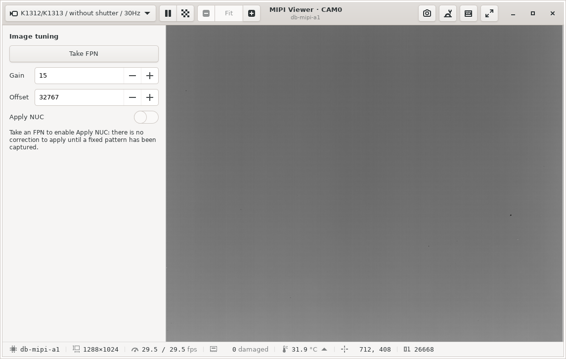
Figure 1: The window of a board on CAM0, streaming a K1313.
The window has four areas:
Area |
Contents |
|---|---|
Header bar |
The setup, the stream and zoom controls, and the tools. The title names the connector, and the subtitle the board’s driver. |
Side column |
The message strip, the activity strip and Image tuning. |
Stream |
The video from the board. |
Status bar |
Information about the MIPI board, the setup and its video: see Read-outs. |
The header bar holds, from left to right:
Control |
Use it to |
|---|---|
Setup chooser |
Choose the setup and connect it. It shows the connected setup, or Select setup… when there is none. See Connecting a setup. |
Pause / Resume |
Freeze the image, and let it run again (space). |
Test pattern |
Show the MIPI board test pattern instead of the sensor image (#). |
Zoom |
Zoom out ( |
Capture |
Save images from the stream. See Capturing images. |
Custom commands |
Read and write the registers of the setup’s components. See Custom commands. |
Keyboard shortcuts |
List every key (F1). |
Fullscreen |
Show the image alone, on the whole screen (f). |
A control that cannot act is greyed out. Most need a connected setup; the custom commands work without one. While an operation such as taking an FPN runs, the controls that act on the board wait for it to end.
Messages
Everything the viewer has to report appears in the message strip, at the top
of the side column. Information fades after a few seconds; a warning or an
error stays until it is closed with its ×.
A long operation, taking an FPN or saving a burst of images, shows in the activity strip below it, with what it is doing, its progress when it has one, and a Stop button when it can be stopped.
Connecting a setup
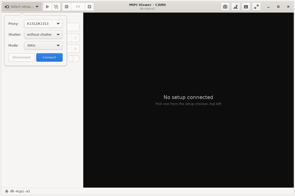
Figure 2: Choosing a setup, before any is connected.
Click the setup chooser, top left, choose the setup, then click Connect. The popover offers up to three selectors, each listing what fits the choice above it:
Selector |
Lists |
|---|---|
Proxy |
The setups the configuration file declares for this board’s driver, by their proxy. |
Shutter |
The shutter variants of that setup, such as with shutter and without shutter. |
Mode |
Its frame rates, such as 30Hz and 60Hz. |
A selector is left out when the setup declares nothing on it: a proxy with its own oscillator has no mode, and an MD-MZ-I313 has neither shutter nor mode.
Connect configures the MIPI board for the setup, writes the setup’s startup registers and starts the stream. The window then resizes so that the image is the frame drawn at a whole number of screen pixels per sensor pixel, as large as the screen allows. A frame larger than the screen is drawn smaller, keeping its shape. A window resized by hand is left alone when the next setup has the same frame size.
Changing a selector while a setup is connected changes nothing until Reconnect is clicked. Disconnect stops the setup’s sensor and lets go of it; the window stays open on the MIPI board. Closing the window does the same.
A connection the MIPI board cannot honour is refused, in the message strip, with the reason:
Refused because |
Meaning |
|---|---|
It declares a component this MIPI board has no way to reach |
The setup description declares a component, such as a proxy, the sensor, its ISP or a shutter, that the MIPI board’s driver cannot reach. |
It declares a frame this MIPI board cannot be put into |
The MIPI board does not accept the setup’s frame size. |
Its startup sequence writes to a component this MIPI board cannot write |
A startup register is written to a component the MIPI board cannot write. |
The MIPI board did not answer |
Nothing answered when the MIPI board was configured: it may not be connected, or not powered. |
A refusal leaves no setup connected, even when another one was connected before.
Note
When the configuration file has problems, a configuration problems section at the top of the popover lists them, with the file they were found in. A setup missing from the selector is usually explained there. See The configuration file.
Watching the image
Pausing and the test pattern
Pause (space) freezes the image on the next frame. The board keeps streaming underneath, and the read-outs answer for the frozen frame. Resume with the same button or key.
The test pattern (#) is generated by the MIPI board’s FPGA and replaces the sensor image, which makes it a check of the link from the board to the screen. It is offered only on MIPI boards that have one. While it is up, the non-uniformity correction is switched off, since it describes the sensor image, and Image tuning is paused; taking the pattern down puts the correction back as it was.
Note
A test pattern built into a proxy board is a different thing. It is set through the proxy’s registers, in Custom commands.
Zooming
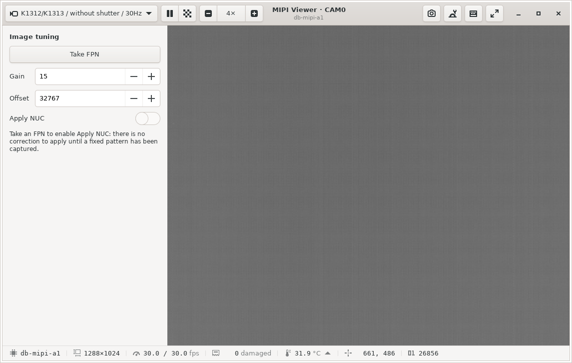
Figure 3: The same image at 4×.
The image zooms in steps: Fit, 2×, 3×, 4×, 6× and 8×. The middle of the zoom group reads the current step, and clicking it goes back to the whole frame.
Action |
Gesture |
|---|---|
Zoom in, about the middle |
|
Zoom out |
|
Back to the whole frame |
The step reading, 0 |
Zoom in or out, about the pointer |
The wheel over the image |
Zoom in on a point, and back |
Double-click the image: 2× about that point, then back to Fit |
Pan the zoomed image |
Drag it, with the left or the middle button |
Each sensor pixel is drawn as a square, without interpolation, so that its value can be read off the screen. The picture stays where it is on screen at every step: less of the frame is shown, larger.
Zooming only changes what is on screen: captures and the FPN always use the whole frame. The zoom can only be changed while the stream is not paused.
Fullscreen
f, or the fullscreen button, shows the image alone on the whole screen: the header bar, the side column and the status bar are hidden, and the pointer hides once it has been still for two seconds. Escape comes back. Every keyboard shortcut still works in fullscreen.
Read-outs

Figure 4: The status bar, with the pointer over the image.
The status bar, along the bottom of the window, gives information about the
MIPI board, the setup and its video. Hovering a read-out names it. A value that is not available shows
— in its place, rather than disappearing.
Read-out |
Shows |
|---|---|
Board |
The Linux driver of the MIPI board. Only setups declaring this driver are offered. Shown with or without a setup connected. |
Resolution |
The frame the board is sending, in pixels. |
Frame rate |
The frames the board sends each second, then how many of those the screen draws. The second is paced by the display and is often lower; the first is the board’s. It turns red when no frame is arriving. |
Damaged frames |
The frames the receiver flagged since the setup was connected. They are shown all the same, though parts of them may be wrong. The count is red while it is growing. Some receivers flag the first frames of every stream. |
Sensor temperature |
The sensor (FPA) temperature in °C, from the source chosen as described below. |
Pixel |
The column and row of the frame pixel under the pointer. |
Raw |
What the sensor sent for that pixel, as a 16-bit value: before the correction, the gain and the offset the image is shown through. |
The setup’s read-outs only appear while a setup is connected. They refresh every second; the pixel read-out every tenth of a second while the pointer is over the image.
Temperature source
The sensor (FPA) temperature may be read in more than one way. When the setup offers several, the temperature read-out carries an arrow, and clicking it chooses the source:

Figure 5: The temperature sources of a K1313.
Source |
Read from |
|---|---|
MIPI board ADC |
The sensor’s VTemp analog output, measured by the MIPI board. |
VTemp column |
The VTemp the sensor sends with its video. |
Sensor ISP |
The sensor’s ISP, while the stream runs. |
Both VTemp readings are converted to °C with the setup’s coefficients from the configuration file.
The choice is kept for the next setup connected. A setup that does not offer the chosen source is read from its first one, and the message strip says which.
Image tuning
The image is shown in 256 grey levels, from the top eight bits of each 16-bit value. Image tuning, in the side column, applies a non-uniformity correction before that:
shown = (raw - FPN) * gain + offset clamped to 0 to 65535
Control |
Effect |
|---|---|
Take FPN |
Captures the fixed pattern, averaging 16 frames (s). On a setup with a shutter, the shutter is closed for it and opened again after. Damaged frames are left out. |
Gain |
0 to 255, from 15. t and g step it by 1. |
Offset |
0 to 65535, from 32767. o and l step it by 200. |
Apply NUC |
Shows the corrected image (n). Offered once an FPN has been taken. |
Gain and offset act on the corrected image only: they change nothing on screen until Apply NUC is on. They take effect as they change.
Warning
On a setup without a shutter, the fixed pattern is taken from whatever the sensor sees. Put a thermally uniform target in front of it first, or the scene is subtracted from every frame that follows.
The FPN belongs to the setup it was taken on: connecting a setup, the same one again included, discards it and switches the correction off. While the group is unavailable, a note under it says why.
Capturing images
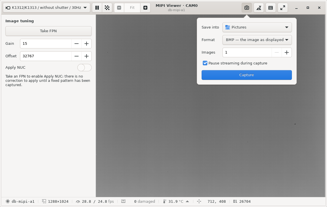
Figure 6: The capture settings.
The capture button, at the right of the header bar, opens the capture settings. They are read when Capture is clicked:
Setting |
Meaning |
|---|---|
Save into |
The folder the images are written to. It starts at the Pictures folder, or the home folder where there is none. |
Format |
BMP, the image as displayed, or RAW, the sensor data as sent. |
Images |
1 to 9999. More than one is a burst, one frame per saved image. |
Pause streaming during capture |
Freezes the image on screen while the images are saved, and lets it run again after. On by default. |
The two formats hold different things:
Format |
File contents |
|---|---|
BMP |
A 24-bit grey image, as shown: with the correction, the gain and the offset when Apply NUC is on. |
RAW |
The frame’s 16-bit samples, row by row, little-endian, with no header: width × height × 2 bytes, as the Raw read-out reads them. |
Both always hold the whole frame, whatever the zoom. Files are named after the setup and the time of the capture, numbered in a burst:
snapshot_K1312_K1313_without_shutter_30Hz_2026-10-14_15-02-11.bmp
snapshot_K1312_K1313_without_shutter_30Hz_2026-10-14_15-02-11_0001.raw
The burst shows in the activity strip, where Stop ends it early; the images already written are kept. The message strip then names the folder and says how many images were saved, and how many came from damaged frames. A frame that does not come, or a full disk, ends the burst at the first failure.
Custom commands
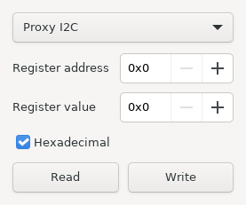
Figure 7: A custom commands window, on the proxy’s I2C registers.
The custom commands button (r) opens a window to read and write the registers of the setup’s components. Each press opens one more window, so that two components, or two registers of one, are at hand together. A window closed is kept with what was typed in it, and the next press brings it back first.
Component |
Address, value |
Offered when |
|---|---|---|
Proxy SPI |
4, 12 bits |
The proxy board is reachable through SPI. Write only. |
Proxy I2C |
16, 8 bits |
The proxy board is reachable through I2C. |
Sensor ISP |
16, 16 bits |
The sensor has an embedded ISP, as on the MD-MZ-I313. |
Sensor |
16, 8 bits |
The setup declares its sensor reachable on I2C. |
Choose the component at the top, enter the address, then Read or
Write.
Enter in the address field reads it; in the value field it writes the
value. Numbers may be typed in decimal or hexadecimal, 63, 0x3F or
3F; Hexadecimal sets how they are displayed. A failed read or write is
reported in the board window’s message strip.
Warning
Writes go to the hardware as typed. The viewer only checks that they fit the register width; what a value does is for the proxy board’s or the sensor’s datasheet to say.
Before a setup is connected, the window offers every component the MIPI board’s driver can reach. Once a setup is connected, it offers those the configuration file declares reachable for that setup. A window with no component left to show closes.
Keyboard shortcuts
F1, or the keyboard button, lists every key in a window of its own.
Key |
Action |
|---|---|
space |
Pause or resume the image. |
f, Escape |
Fullscreen the image, and leave fullscreen. |
# |
MIPI board test pattern. |
+, -, 0 |
Zoom in, zoom out, back to the whole frame. |
s |
Take FPN. |
n |
Apply NUC. |
t, g |
Gain +1, gain −1. |
o, l |
Offset +200, offset −200. |
r |
Open a custom commands window. |
F1 |
Keyboard shortcuts. |
Ctrl-N |
Open a window on another MIPI board. |
Ctrl-W |
Close this window. |
Ctrl-Q |
Quit, closing every window. |
A key whose action is unavailable does nothing. While a field is being typed into, letters and digits go to the field.
The configuration file
The setups the viewer offers are described in a TOML file. The viewer reads the first of these that exists, once at startup:
File |
Use |
|---|---|
|
The user’s own, replacing the system file as a whole. |
|
The system file, installed with the package. |
The installed file starts with a summary of its format and describes every supported setup; copying it is the simplest way to start a file of one’s own.
Structure
Four kinds of table build a setup, each level overriding the keys of the one above it:
Table |
Declares |
|---|---|
|
Keys shared by every setup on that driver. |
|
A setup, in the Proxy selector, and its MIPI board’s driver. |
|
A variant in the Shutter selector. |
|
A frame rate in the Mode selector. |
A setup’s own shutter or mode list replaces its driver’s. Startup registers add up instead of overriding, and are written on connection in that order: driver, setup, shutter, mode.
For example, a setup with two frame rates and the driver’s shutter variants:
[setup."K1312/K1313"]
driver = "db-mipi-a1"
proxy_i2c_reachable = true
column_vtemp_reachable = true
resolution_width = 1288
resolution_height = 1024
video_range_min = 0.3
video_range_max = 2.7
offset_vtemp = 410.42
coef_dir_vtemp = -187.775

# Reset the proxy firmware, which a MasterClock stop may leave in protection mode
[[setup."K1312/K1313".startup_register]]
target = "i2c_proxy"
address = 0x08
value = 0x00

[setup."K1312/K1313".mode."30Hz"]
m_div_coef = 13
n_div_coef = 205
output_div_coef = 96
Setup keys
Key |
Meaning |
|---|---|
|
|
|
|
|
|
|
|
|
|
|
|
|
|
|
The sensor line width and frame height, in pixels. Required on
|
|
The sensor clock: M, N, and the raw |
|
The volts the VTemp column’s word 0 and its full scale stand for. Without them, no temperature is read from the VTemp column. |
|
The VTemp to temperature line: offset in °C, slope in °C/V. Without them, no temperature is read from VTemp at all, neither from the MIPI board ADC nor from the VTemp column. |
Each [[...startup_register]] entry is written on connection:
Key |
Meaning |
|---|---|
|
|
|
The register address. |
|
The value to write. |
|
Optional: a pause after the write, in ms. |
Problems in the file
A mistake in the file is reported when the viewer starts. The part concerned is skipped and the rest is used: a setup with an error is left out of the selector, and an unknown key is ignored. Each board window then says, in its message strip, how many problems were found, and the setup chooser lists them under configuration problems, with the path of the file. The text can be selected, to search for a line in the file.
A file that cannot be read or parsed offers no setup at all, and the image placeholder says so.
Messages and limits
Message |
What it means |
|---|---|
No MIPI board found |
Its driver may not be loaded, or its overlay not applied. |
Could not open: … |
The board was found but could not be opened, for the reason given on its row of the chooser. |
The configuration file describes no setup for this board |
No setup in the file declares the board’s driver. |
Cannot connect … |
Connecting the setup failed. The rest of the message says why: see Connecting a setup. |
Frame rate in red |
A setup is connected and the stream is not paused, but no frame arrives. |
Damaged frames in red |
The receiver keeps flagging frames as damaged. |
The shutter did not close: the fixed pattern was not captured |
The shutter was told to close and did not report it. The image and the previous FPN are unchanged. |
No frame arrived |
A frame was waited for and did not come: the FPN or the capture ended there. |
Every frame arriving was damaged |
The FPN found no undamaged frame to average. |
Saved … images to … |
The capture is complete, with the number from damaged frames if any. |
Choose a folder to save the images into |
The capture folder is not set. |
… register 0x…: read failed, write failed |
The board did not complete a custom command. |
Two limits are worth keeping in mind:
The image and the BMP captures show eight bits of each pixel. The Raw read-out and the RAW captures carry all sixteen.
The second frame rate is the display’s, not the board’s: a window on a slow display, or a remote desktop, draws fewer frames while the board keeps its rate.
Revision history
Date |
Author(s) |
Version |
Comments |
|---|---|---|---|
10/2026 |
F. DESCAMPS |
Rev. A |
First document release |